Product Overview
The SeaSonde AutoAPM Kit automatically tests the quality of an existing antenna pattern (AP) as well as generates autonomous SeaSonde APs. AP quality metrics are calculated using Doppler echoes from passing vessels as a signal source and their AIS transponder data for a reference bearing. The automated output is useful in system calibration, routine system monitoring and maintenance for maximizing quality assurance of your SeaSonde data products. AP data is collected in real time on the site and updated pattern data produced when the quality of the existing pattern drops. This technology may reduce the need for additional transponder measurements, or be used to identify times when a new transponder measurement or hardware inspection is necessary.
FUNCTIONALITY
The AutoAPM Kit works to automatically:
Monitor Existing (Installed) Antenna Pattern Quality
The software assesses how well the existing installed pattern running at the site is working by several different methods:
• Testing for error in bearing assignment, by comparing the MUSIC-assigned bearing vs. AIS-matchup bearing of same target, generating a quantified estimate of the actual error. For this the software looks in the cross spectra to find peaks of possible vessel echoes. Once those peaks are tagged they are matched with the AIS tracks to assign them a bearing and matched through range and velocity at a given time;
• Calculating the correlation between the direction-finding (DF) MUSIC bearing solution and AIS bearing lookup of same target;
• Comparing radial distribution from one time frame to the next, and measuring the divergence of the distribution at each time step. A change in radial distribution can indicate a change in the real AP or another site issue that requires attention. The system creates a new comparison radial distribution automatically once per day using all radial vectors from the previous five days. This feature can be initiated manually or set for auto-repeat at a custom time interval.
Look for Antenna Rotation
The system also monitors for signs of the receive antenna rotation. The correlation between DF MUSIC bearing and AIS bearing lookup can remain good when an antenna rotation has taken place, so the software also looks for evidence of antenna rotation by looking for a vertical shift in the bearing error of the antenna pattern. The system calculates the average degree to which the bearing has been shifted. Antenna rotation also impacts validity of the pattern running at the site and bearing angle settings in software as well as indicator the antenna may need to be re-secured to its mount.
 Generate New Antenna Patterns
When vessel DF bearings reach correlation threshold with AIS bearings, or when a change in correlation is detected, the system automatically generates a new AP. The user can also choose to process a new pattern at any time. The amount of time needed to create a new pattern is based on the level of local vessel traffic, which may vary by direction or time. The bearing coverage is also dependent upon path of passing AIS vessels. New pattern will only cover the bearing sectors in which AIS peaks are collected. The pattern may or may not cover enough bearing sectors to be used as a site’s active installed pattern but can always be used as an ongoing quality comparison tool.
Calculate Optimal Pattern Smoothing
Before recommending a particular level of smoothing for a new pattern, the software tests new AIS pattern using different degrees of smoothing (0 – 300 ) to see which gives the best DF results.
Compare Installed Antenna Pattern with New AIS & Ideal Patterns
The software automatically compares installed pattern with both AIS-derived and ideal patterns to assess which would perform best.
Output New Pattern Recommendations
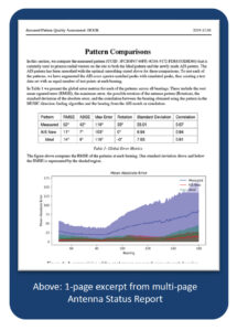
All findings are presented in an Antenna Status Report – updated daily – that also includes a summary recommendation whether or not an installed AP should be replaced with a new pattern. If the software can generate a new pattern covering enough bearing sectors to be used as a replacement pattern then the location of new pattern within system is noted along with the recommended degrees of smoothing to which should be optimally applied.
CODAR Ocean Sensors, Ltd. www.codar.com


